Brand sort
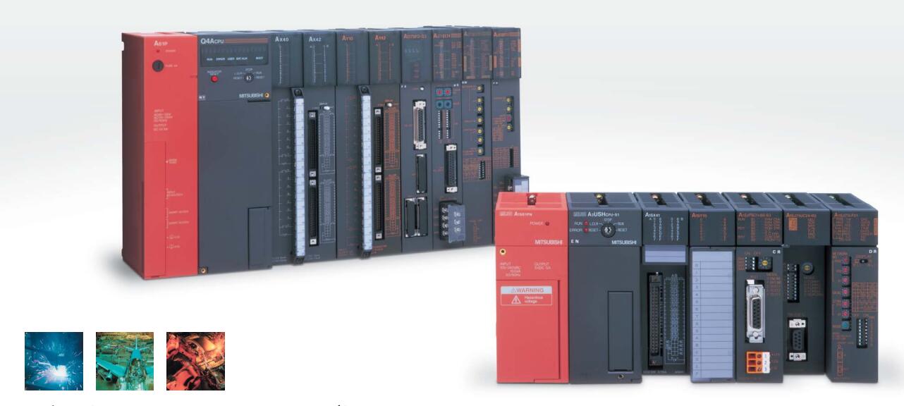
MITSUBISHI A0J2-PW Market price | A0J2-PW Introduction
Brand:
MITSUBISHI
Country: JAPAN
Name: AC input module
Model: A0J2-PW
Market price: U.S.$ 101.69
(The following are the market open price not sales price!)
(The following are the market open price not sales price!)
MITSUBISHI A0J2-PW
Drive unit.
MITSUBISHI universal AC servo amplifier MELSERVO-J4 series.
Rated output: 30kw.
Interface: universal type.
Power supply: three phase AC400V.
Special specifications: full closed control 4 wire / support mechanical end encoder ABZ phase input / support positioning mode.
Support position control, speed control, torque control.
Position control to follow the position instructions.
When the control is inserted, the position control is performed A0J2-PW
Speed control follows the speed command to control the speed within a certain range.
Torque control to follow the torque command to control the stable torque.
Function of switching amplitude. The increase in the process of switching and stopping,
And in the operation of the use of the switching signal, switching growth. MITSUBISHI general purpose AC servo amplifier MR-J2 series.
Rated output: 0.2kw.
Interface: general purpose interface.
Voltage: single phase AC100V.
MITSUBISHI servo system in the MITSUBISHI servo amplifier is widely used,
It can not only be used in the high precision position control and speed control of the working machinery and general industrial machinery,
Can also be used in the field of speed control and tension control.
By installing a personal computer with a servo setting software, the parameters setting, trial run, state display, and gain adjustment are performed.
MITSUBISHI servo system MR-J2S column is developed on the basis of the servo MR-J2 series with a higher performance and more features of the MITSUBISHI servo system,
The control modes are position control, speed control and torque control, as well as the switching control mode among them. Protective film for 12.1 inch screen.
Scrub (frame: white), 5.
Applicable model: GT15. Remote I/O controller, coaxial cable.
How to choose MITSUBISHI PLC.
MITSUBISHI PLC options include the choice of MITSUBISHI PLC models, capacity, I/O module, power, etc..
MITSUBISHI PLC distribution I/O points and design MITSUBISHI PLC peripheral hardware circuit
Draw the I/O point of the PLC and the input / output device connection diagram or the corresponding table,
This part also can be carried out in second steps.
Design PLC peripheral hardware circuit.
Draw the electrical wiring diagram of the other parts of the system,
Including the main circuit and the control circuit does not enter the PLC, etc..
The electrical schematic diagram of the system composed of I/O PLC connection diagram and PLC peripheral electrical circuit diagram.
So far the system''s hardware electrical circuit has been determined.
A0J2-PW Operation manual / Instructions / Catalog download link: /searchDownload.html?Search=A0J2-PW&select=5
...more relevant model market price >>>>
Related products
MITSUBISHI
CPU unit
A0J2CPUR23
Input and output points: 480 points.
Pro
MITSUBISHI
CPU unit
A0J2CPU-DC24
Input and output points: 480 points.
Pro
MITSUBISHI
Connecting cable
A0J2-C01
Cale for unit load.
Length: 80mm.
Input
Related download


 next one:
  Last one: