
Home
>> Products
>> MITSUBISHI
>> CC-Link module
>> Remote I/O module
>> AJ65VBTCE3-16D | MITSUBISHI Sensor connector type input module AJ65VBTCE3-16D
AJ65VBTCE3-16D | MITSUBISHI Sensor connector type input module AJ65VBTCE3-16D
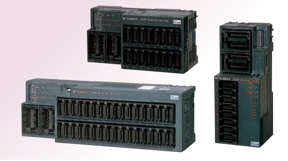
MITSUBISHI AJ65VBTCE3-16D Manual And Instructions
AJ65VBTCE3-16D datasheetPDF datasheet
MITSUBISHI AJ65VBTCE3-16D Product information and technical parameters:
Brand: MITSUBISHI
Name: Sensor connector type input module
Model: AJ65VBTCE3-16D
Input type: DC input, positive common end.
Input points: 16 points.
Enter the response time: 1.5ms the following.
Rated input voltage / current: DC24V/5mA.
External connection: 3 wire.
Sensor connector type (E-CON type).
Using industry standard E-CON type.
Simple wiring through sensor connector.
When installing the module can choose to use the DIN guide rail or screw mounting.
3 wire sensor input.
...More relevant models >>>>
AJ65VBTCE3-16D datasheetPDF datasheet
MITSUBISHI AJ65VBTCE3-16D Product information and technical parameters:
Brand: MITSUBISHI
Name: Sensor connector type input module
Model: AJ65VBTCE3-16D
Input type: DC input, positive common end.
Input points: 16 points.
Enter the response time: 1.5ms the following.
Rated input voltage / current: DC24V/5mA.
External connection: 3 wire.
Sensor connector type (E-CON type).
Using industry standard E-CON type.
Simple wiring through sensor connector.
When installing the module can choose to use the DIN guide rail or screw mounting.
3 wire sensor input.
Output type: transistor output, source.
Output points: 8 points.
OFF leakage current: 0.1mA.
Output protection function.
Rated load voltage / current: DC12V/DC24V/0.1A.
External connection: 2 wire.
Spring clip terminal.
Do not need to re tighten, suitable for wire specifications for 0.3~1.5MM square MITSUBISHI AJ65VBTCE3-16D.
Terminal block is 2 piece structure.
An input module shared by the common terminal of the positive and negative AJ65VBTCE3-16D
The 8 point of the output module is appended to the source type.
Can be installed along the 6 direction. Input type: DC input, positive common end.
Input points: 8 points.
Input response time: 0.5ms below /1.5ms.
Rated input voltage / current: DC24V/4mA.
External connection: 3 wire.
Sensor connection type MITSUBISHI AJ65VBTCE3-16D.
Minimum size of industry.
When installing the module can choose to use the DIN guide rail or screw mounting.
3 wire sensor input. RS-232 1 channels.
With DC input 2 points.
Transistor output 2.
Number of stations: 1 stops.
Station type: intelligent equipment station.
MITSUBISHI PLC online debugging.
On-line debugging is the process that will through the simulation debugging to further carry on the on-line unification to adjust MITSUBISHI AJ65VBTCE3-16D.
On-line debugging process should be step by step,
From MITSUBISHI PLC only connected to the input device, and then connect the output device, and then connect to the actual load and so on and so on step by step.
If you do not meet the requirements, the hardware and procedures for adjustment.
Usually only need to modify the part of the program can be.
MITSUBISHI PLC hardware implementation
Hardware implementation is mainly for the control cabinet and other hardware design and field construction.
Design control cabinet and the operating table and other parts of the eelectrical wiring diagram and wiring diagram AJ65VBTCE3-16D.
Electrical interconnection diagram of each part of the design system.
According to the construction drawings of the site wiring, and carry out a detailed inspection.
Because the program deesign and hardware implementation can be carried out at the same time,
So the design cycle of the MITSUBISHI PLC control system can be greatly reduced AJ65VBTCE3-16D.
...More relevant models >>>>
 Last one: MITSUBISHI Sensor connector type input module AJ65VBTCE3-8D
 next one: MITSUBISHI Sensor connector type input module AJ65VBTCE3-32D
Related download