Brand sort
MITSUBISHI MR-J3-60A4 Market price | MR-J3-60A4 Introduction
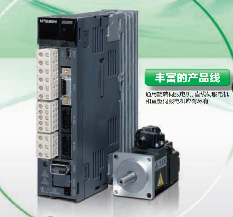
MITSUBISHI MR-J3-60A4
The most appropriate temperature regulation control (PID control) is possible,
In order to control the PID does not need to specify a special command.
In addition, according to the automatic regulation function,
The automatic setting of PID number is possible.
The length of time required to execute the instruction, the length of the user''s program, the type of instruction, and the speed of the CPU execution are very significant,
Generally, a scanning process, the fault diagnosis time,
Communication time, input sampling and output refresh time is less,
The execution time is accounted for the vast majority of MR-J3-60A4
The response time of PLC is the interval between the time of the change of the external output signal of the PLC and the time of the change of the external output signal which is controlled by it,
Lag time, this is the time constant of the input circuit,
The time constant of the output circuit, the arrangement of the user statement and the use of the instruction,
The cycle scan mode of PLC and the way of PLC to refresh the I/O and so on.
This phenomenon is called the I/O delay time effect. Max input / output points: 14 points.
Power supply voltage: DC24V.
Input points: 8 points.
Output points: 6 points.
Output type: relay.
Power consumption (W): 32.
Weight (kg):0.4.
Size (WxHxD) mm:90x90x75.
FX1N series is a very powerful micro PLC, can be extended to up to 128 I/O points,
And can increase the special function module or the expansion board.
Communication and data link function options make FX1N in the volume, communication and special function modules and other important applications is very perfect.
A PLC unit can output 2 100KHz pulses at the same time,
PLC is equipped with 7 special positioning instructions,
Including zero return, absolute position readout, absolute or relative drive, and special pulse output control. Connect to read and write 2Ch.
ID system interface module.
ID controller M-688-001/002 BIS can be installed directly to the Q series of substrates,
Control module for reading and writing ID tag data through a programmable logic controller.
The ladder diagram of M-688-002 BIS is compatible with QD35ID1/2.
2 antennas can be connected, and the parallel processing of the 2 channels can be simultaneously carried out.
Can use all ID tags in the M BIS series.
ID series /BIS system is an industrial automation ID system which can use the electromagnetic combination method to read and write data.
ID tag has a variety of sizes and storage capacity.
MR-J3-60A4 Operation manual / Instructions / Catalog download link: /searchDownload.html?Search=MR-J3-60A4&select=5
...more relevant model market price >>>>
Related products
MITSUBISHI
Universal pulse interface driver
MR-J3-DU55KA4
Drive unit 200VAC/400VAC level.
MITSUBIS
MITSUBISHI
Monitoring cable
MR-J3CN6CBL1M
Line length: 1m.
MITSUBISHI
SSCNET type III optical fiber communication driver
MR-J3-20B
MITSUBISHI motor universal AC servo ampl
MITSUBISHI
For direct drive servo motor drive
MR-J3-500B-RJ080W
MITSUBISHI motor universal AC servo ampl
Related download


 next one:
  Last one: