
Home
>> Products
>> MITSUBISHI
>> Ans/QnAs series PLC
>> Output module
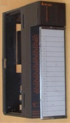
>> A1SY18A | MITSUBISHI Relay output module A1SY18A
A1SY18A | MITSUBISHI Relay output module A1SY18A
MITSUBISHI A1SY18A Manual And Instructions
A1SY18A datasheetPDF datasheet
A1SY18A User's Manual
MITSUBISHI A1SY18A Product information and technical parameters:
Brand: MITSUBISHI
Name: Relay output module
Model: A1SY18A
Output type: relay.
Output points: 8 points.
Load voltage: AC240/DC24.
Load current: 2A.
Connection mode: terminal row.
Common public end points: 1.
Structured text language is a programming language that describes a program with a structured description of the text.
It is a programming language similar to a high level language. In large and medium
Structured text is often used to describe the relationship between the various variables in the control system based on the PLC system.
Mainly used for other programming languages more difficult to achieve the user program.
The structured text programming language uses the computer description method to describe the various kinds of relations between the various variables in the system,
Complete the required function or operation.
Most PLC manufacturers use structured text programming language similar to BASIC language, PASCAL language or C language and other advanced languages,
But in order to be convenient, the expression methods of the statement and the types of statements are simplified.
Structured text programming language features: the use of high-level language programming, you can complete the complex control operations,
Need to have a certain level of computer knowledge and programming skills,
Higher requirements for engineering designers. Poor visibility and operability.
...More relevant models >>>>
A1SY18A datasheetPDF datasheet
A1SY18A User's Manual
MITSUBISHI A1SY18A Product information and technical parameters:
Brand: MITSUBISHI
Name: Relay output module
Model: A1SY18A
Output type: relay.
Output points: 8 points.
Load voltage: AC240/DC24.
Load current: 2A.
Connection mode: terminal row.
Common public end points: 1.
Structured text language is a programming language that describes a program with a structured description of the text.
It is a programming language similar to a high level language. In large and medium
Structured text is often used to describe the relationship between the various variables in the control system based on the PLC system.
Mainly used for other programming languages more difficult to achieve the user program.
The structured text programming language uses the computer description method to describe the various kinds of relations between the various variables in the system,
Complete the required function or operation.
Most PLC manufacturers use structured text programming language similar to BASIC language, PASCAL language or C language and other advanced languages,
But in order to be convenient, the expression methods of the statement and the types of statements are simplified.
Structured text programming language features: the use of high-level language programming, you can complete the complex control operations,
Need to have a certain level of computer knowledge and programming skills,
Higher requirements for engineering designers. Poor visibility and operability.
Input and output points: 512 points.
Input / output data points: 8192 points.
Program capacity: 14K.
Basic command processing speed (LD command) s:0.2.
Internal storage RAM memory capacity: 64K
PLC in the program execution stage: according to the order of the user program order to store the order of each instruction,
After the corresponding operation and processing, the result is written to the output status register,
The contents of the output status register are changed with the execution of the program MITSUBISHI A1SY18A A1SY18A
Output refresh phase: when all instructions are executed,
The output status register is sent to the output latch in the output refresh stage,
And through a certain way (relay, transistor or transistor) output, drive the corresponding output equipment MITSUBISHI A1SY18A. . I/O slots: 5 slots.
Outline dimension: 325*130.
CPU basic board can be plugged into 1 power modules,
1 CPU components and a maximum of 2, 3, 5, or 8 single slot size special function components and I/O components are respectively inserted and arranged.
Expansion ports are arranged on both sides of the base plate,
For connecting the expansion board for MITSUBISHI A1SY18A.
Up to 3 extension substrates. A1SCPUC24-R2 integrates all functions of A1SCPU with a dedicated RS232 interface,
It maintains the compatibility of CPU ANS and is easy to use.
The built-in RS232 interface makes it can connect bar code reader, operator interface, computer and so on,
Realization of low cost data communication.
A1SCPUC24-R2 is a combination of A1SCPU and A1SJ71C24-R2 features of the two components together.
It maintains the compatibility and communication specifications for the two component programming.
Fixed this A1SCPU and A1SJ71C24-R2 programming method applied to A1SCPUC24-R2. Output type: relay.
Output points: 16 points.
Load voltage: AC120/DC24.
Load current: 2A.
Connection mode: terminal row.
Common public end points: 8.
Sequential function flow chart language is designed to satisfy the sequential logic control.
The process of sequential process action is divided into steps and transformation conditions,
According to the transfer condition, the control system is distributed in the function flow sequence,
Step by step according to the sequence of actions.
Each step represents a control function, represented by the box.
In the box, the ladder logic is used to complete the task of the corresponding control function.
This programming language makes the program structure clear and easy to read and maintain,
Greatly reduce the programming workload, shorten the programming and debugging time.
Used in the system of the size of the school, procedures for more complex occasions.
Sequence function flow chart programming language features: to function as the main line, in accordance with the functiional flow of the order of distribution, clear, easy to understand the user program,
Avoid the defect of ladder diagram or other languages,
At the same time, the use of ladder language to avoid the use of ladder programming,
Due to the compllicated mechanical interlock, the structure of the user program is complex and difficult to understand,
User program scan time is also greatly reduced A1SY18A A1SY18A.
...More relevant models >>>>
 Last one: MITSUBISHI Relay output module A1SY14EU
 next one: MITSUBISHI Relay output module A1SY18AEU
Related download