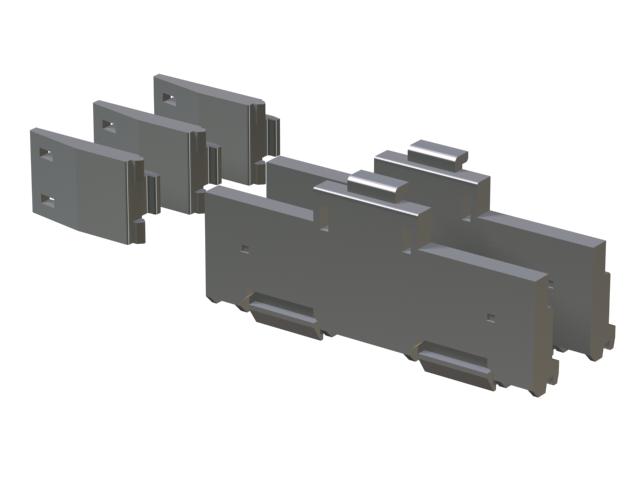
Brand sort
MITSUBISHI Q6DIN2 Market price | Q6DIN2 Introduction
Brand:
MITSUBISHI
Country: JAPAN
Name: Adapter
Model: Q6DIN2
Market price: U.S.$ 15.25
(The following are the market open price not sales price!)
(The following are the market open price not sales price!)
MITSUBISHI Q6DIN2
RS-232:1 channel, RS-422:1 channel.
BASIC program mode (A3MCPU corresponding): BASIC console interface to use.
Sequential program mode (program controller CPU correspondence): non sequential computer connection interface and use.
How to choose MITSUBISHI PLC.
MITSUBISHI PLC options include the choice of MITSUBISHI PLC models, capacity, I/O module, power, etc..
MITSUBISHI PLC distribution I/O points and design MITSUBISHI PLC peripheral hardware circuit
Draw the I/O point of the PLC and the input / output device connection diagram or the corresponding table,
This part also can be carried out in second steps Q6DIN2
Design PLC peripheral hardware circuit.
Draw the electrical wiring diagram of the other parts of the system,
Including the main circuit and the control circuit does not enter the PLC, etc..
The electrical schematic diagram of the system composed of I/O PLC connection diagram and PLC peripheral electrical circuit diagram.
So far the system''s hardware electrical circuit has been determined. Power: 560kw.
Purpose: to suppress the power harmonics.
Connected to the inverter input, can be used to improve the power factor, reduce the input side of the high harmonic current.
According to the motor power used to select AC reactor.
(when the inverter capacity is greater than the motor capacity, is still based on the motor capacity to choose.) MITSUBISHI motor universal AC servo amplifier MELSERVO-J3 series.
Rated output: 15.0kw.
Interface type: CC-Link communication type (built-in positioning function).
Power specification: three phase AC400V.
Positioning operation by setting position and rotational speed data in the positioning table and receiving the start signal from the main controller.
The setting of the position and speed of the positioning table, as well as the start and stop operation can be completed through CC-Link communication.
By using the MR-J3-D01 extension IO unit, the DI/O instruction can be used to select and locate the table.
(CC-Link can not be used for MR-J3-D01 communications).
With built-in positioning function of the servo amplifier, can be set through the CC-Link communications and speed data. (corresponding to the CC-Link version: Ver.1.10)
Can be achieved through the CC-Link communications to start, stop and monitoring and other operations.
Serial communication reduce wiring.
Distributed servo control system can be built by CC-Link communication.
The parameters of unit MR-PRU03 (optional) the parameter setting, operation and monitoring more convenient.
The servo amplifier can be used for speed control operation.
When the two stations are occupied, the speed can be set directly by the remote register.
Q6DIN2 Operation manual / Instructions / Catalog download link: /searchDownload.html?Search=Q6DIN2&select=5
...more relevant model market price >>>>
Related products
MITSUBISHI
Adapter
Q6DIN3
Adapter for mounting DIN guide rail.
For
MITSUBISHI
Adapter
Q6DIN1A
Adapter for mounting DIN guide rail wit
MITSUBISHI
Adapter
Q6DIN2
Adapter for mounting DIN guide rail.
For
MITSUBISHI
Adapter
Q6DIN1
Adapter for mounting DIN guide rail.
For
Related download


 next one:
  Last one: