Brand sort
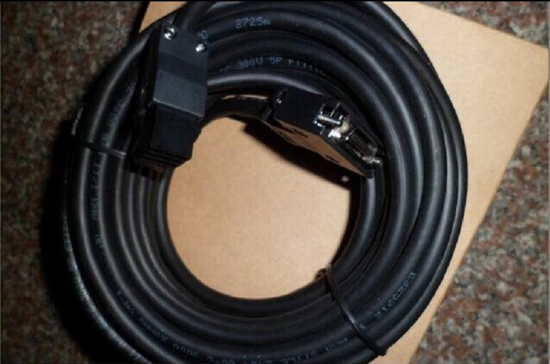
MITSUBISHI MR-J3ENSCBL15M-L Market price | MR-J3ENSCBL15M-L Introduction
MITSUBISHI MR-J3ENSCBL15M-L
A1ST60 analog timer module has 8 analog timers.
Each timer can be set between 0.1-600S,
Its accuracy plus or minus 2%.
Dial setting on the timing constant panel of the timer,
With a small screwdriver can be easily adjusted. Data format: RTU.
Data bits: 8.
A1SJ71UC24-R2-S2 and A1SJ71UC24-R4-S2 allow the Ans series PLC to be connected to the MODBUS network,
As the network from the station, and in accordance with the instructions of the main station of the CPU Ans user storage area for data reading / writing MR-J3ENSCBL15M-L
In addition to supporting the MODBUS protocol, these components also support the standard dedicated communication protocol for A1SJ71UC24 components.
This feature makes the main station of the data acquisition and control with more flexibility.
Support MODBUS slave station protocol.
Supports 1 to 21 function code.
Two transmission modes: RTU or ASCII. Fiber optic cable / twisted pair cable.
Single bus.
Remote I/O station.
According to the control requirements of the system, using the appropriate design method to design MITSUBISHI PLC program.
Procedures to meet the requirements of system control as the main line,
Write one by one to achieve the control function or the sub task of the program,
Gradually improve the functions specified by the system.
MITSUBISHI PLC initialization procedure. After MITSUBISHI PLC on power, the general need to do some of the initial operation,
In order to start making necessary preparations, to avoid the wrong operation of the system.
The main contents of the initialization program are: to some data area, counter and so on,
Data needed to restore some of the data area,
Set or reset some relays,
For some initial state display, etc.. Cable length: 3.0m.
For the connection between QnAS/AnSCPU/ motion controller GOT (A Series) and CPU.
Applicable models: GT16, GT15, GT11. With 4.3 inch widescreen.
Applicable model: GT21. Analog input: 2.
Analog output points: 1 points.
Weight: 0.1kg.
FX3 series can be connected to the 2 channel input (voltage: DC0~10V, or current DC4~20mA), as well as 1 channel output (DC0~10V, or current: DC4~20mA) of the adapter.
Each channel can be specified as a current input or voltage input.
Connecting FX3SA, FX3S, FX3GA, FX3G, and FX3U main body, the need to convert the adapter or function expansion board.
MR-J3ENSCBL15M-L Operation manual / Instructions / Catalog download link: /searchDownload.html?Search=MR-J3ENSCBL15M-L&select=5
...more relevant model market price >>>>
Related products
MITSUBISHI
Encoder cable
MR-J3ENSCBL5M-L
The length of the line: 5m.
IP level: IP
MITSUBISHI
Encoder cable
MR-J3ENSCBL20M-H
The length of the line: 20m.
IP level: I
MITSUBISHI
Encoder cable
MR-J3ENSCBL10M-L
The length of the line: 10m.
IP level: I
MITSUBISHI
Encoder cable
MR-J3ENSCBL20M-L
The length of the line: 20m.
IP level: I
Related download


 next one:
  Last one: