Brand sort
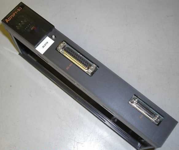
MITSUBISHI AD75P1-S3 Market price | AD75P1-S3 Introduction
Brand:
MITSUBISHI
Country: JAPAN
Name: Positioning module
Model: AD75P1-S3
Market price: U.S.$ 1288.14
(The following are the market open price not sales price!)
(The following are the market open price not sales price!)
MITSUBISHI AD75P1-S3
Input and output points: 24 points.
Power supply: AC100-240V.
Input points: 14 points.
Output points: 10 points.
Output form: relay output.
Power consumption: 32W.
Weight: 0.55KG.
Outline dimension: 90x90x86mm.
EEPROM memory cartridge with program transfer function.
Third generation standard model.
Easy to use integrated models and flexible scalability.
Condensed convenience of using the usual FX3 series AD75P1-S3
Its high price by the most suitable for small scale control.
High speed operation.
Basic instructions: 0.21 s/ instruction.
Application instruction: 0.5 s/ instruction.
Large capacity memory.
Built in program memory 32000 steps.
Auxiliary relay: 7680 points.
Timer: 320 points.
Counter: 235.
Data register: 8000.
Extended register: 24000 point.
Extended file register: 24000.
A free combination of PLC.
FX3G basic unit: 14/24/40/60 point.
FX3GA is a compact PLC, simple design and with the basic functions of the FX3 series.
Through the strengthening of the built-in function and flexible expansion, expanded in various fields of application.
Third generation standard model.
High flexibility.
Suitable for small scale control of high cost.
Control points to 128 points, the use of CC-Link remote I/O can control the maximum 256 points. Smart device site unit (support for CC-LINK Second Edition).
Applicable models: GT15, GT16, GT27, GT25. Number of channels: RS422, 1 channel
.
Configuration of master / local station,
In addition to the other site network with different CC-Link in addition to the main station and the remote station configuration can also be the main station and the local station configuration.
A local PLC can communicate with the master station PLC and other remote workstations.
MITSUBISHI PLC online debugging.
On-line debugging is the process that will through the simulation debugging to further carry on the on-line unification to adjust.
On-line debugging process should be step by step,
From MITSUBISHI PLC only connected to the input device, and then connect the output device, and then connect to the actual load and so on and so on step by step.
If you do not meet the requirements, the hardware and procedures for adjustment.
Usually only need to modify the part of the program can be.
MITSUBISHI PLC hardware implementation
Hardware implementation is mainly for the control cabinet and other hardware design and field construction.
Design control cabinet and the operating table and other parts of the electrical wiring diagram and wiring diagram.
Electrical interconnection diagram of each part of the design system.
According to the construction drawings of the site wiring, and carry out a detailed inspection.
Because the program design and hardware implementation can be carried out at the same time,
So the design cycle of the MITSUBISHI PLC control system can be greatly reduced.
AD75P1-S3 Operation manual / Instructions / Catalog download link: /searchDownload.html?Search=AD75P1-S3&select=5
...more relevant model market price >>>>
Related products
MITSUBISHI
CPU unit
A3NCPUP21-S3
Input and output points: 2048 points.
In
MITSUBISHI
Positioning module
AD75M1
1 axes.
Control unit: pulse, mm, inch, d
MITSUBISHI
Positioning module
AD75P1-S3
1 axes.
2 axis linear interpolation, 2 a
MITSUBISHI
Moving CPU unit
A73CPUP21-S3
Special multi axis positioning controlle
Related download


 next one:
  Last one: