Brand sort
MITSUBISHI R120PCPU Market price | R120PCPU Introduction
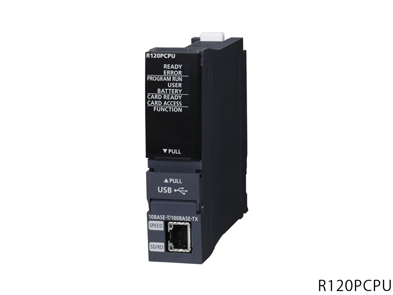
MITSUBISHI R120PCPU
Used to simulate the RGB output.
Applicable model: GT15. Drive: MR-H_ACN series CC-LINK features.
Rated output: 0.2KW.
The test system is composed of two parts, namely, the servo driver, the motor system and the host computer.
The host computer sends the speed command signal to the servo driver,
Servo drives start to run in accordance with the instructions.
In the course of operation, the running data of the servo system is collected by the host computer and the data acquisition circuit,
And carries on the preservation, the analysis and the display to the data R120PCPU Because the motor is not loaded in this test system,
So compared with the previous two kinds of testing systems, the system has a relatively small volume,
And the measurement and control circuit of the system is relatively simple,
But it also makes the system can not simulate the actual operation of the servo drive.
Usually, such testing system is only used to test the rotational speed and angular displacement of the tested system under no-load condition,
And can not carry on the comprehensive and accurate test to the servo drive. Input points: 4 points.
Weight: 0.02kg.
Function expansion board is used in the FX3SA, FX3S, FX3GA, FX3G, FX3GE on the small number of input and output extension of the product,
Can be built into PLC. The length of the line: 20M.
IP level: IP67.
Bending life: high bending life.
Encoder cable for 15K1M, 11K1M4, HF-JP11K1M, 15K1M4. A1S68TD is a 8 channel thermocouple input module,
It can receive almost any type of thermocouple input,
Using Ans CPU A1S68TD system can meet the various requirements of process control applications,
Also has the advantages of all aspects of the ANs can provide.
The length of time required to execute the instruction, the length of the user''s program, the type of instruction, and the speed of the CPU execution are very significant,
Generally, a scanning process, the fault diagnosis time,
Communication time, input sampling and output refresh time is less,
The execution time is accounted for the vast majority of.
The response time of PLC is the interval between the time of the change of the external output signal of the PLC and the time of the change of the external output signal which is controlled by it,
Lag time, this is the time constant of the input circuit,
The time constant of the output circuit, the arrangement of the user statement and the use of the instruction,
The cycle scan mode of PLC and the way of PLC to refresh the I/O and so on.
This phenomenon is called the I/O delay time effect.
R120PCPU Operation manual / Instructions / Catalog download link: /searchDownload.html?Search=R120PCPU&select=5
...more relevant model market price >>>>
Related products
MITSUBISHI
Safety CPU
R120SFCPU-SET
Safety grade SIL: SIL 3 IEC 61508.
P


 next one:
  Last one: