
Brand sort
MITSUBISHI MR-J3-10B-RJ080W Market price | MR-J3-10B-RJ080W Introduction
Brand:
MITSUBISHI
Country: JAPAN
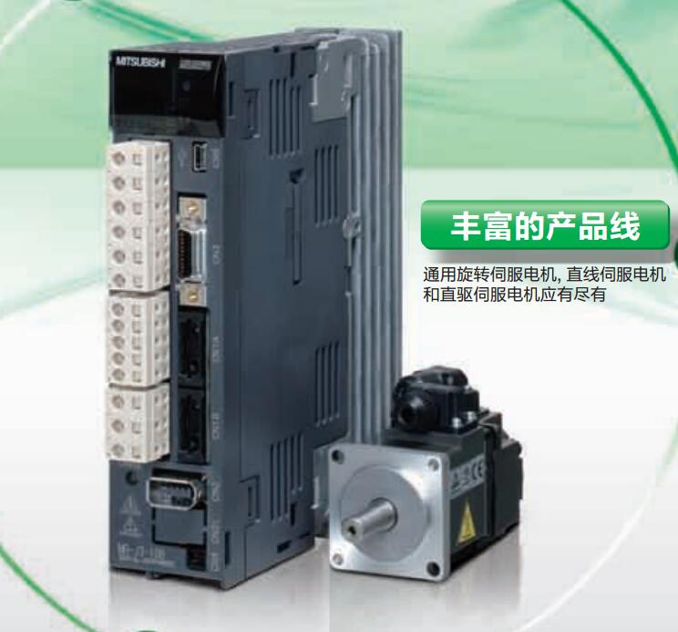
Name: For direct drive servo motor drive
Model: MR-J3-10B-RJ080W
Price: 0
 next one:
  Last one:
 MITSUBISHI MR-J3-10B-RJ080W
Cable length: 10 meters.
QnACPU GOT.
RS-422 conversion (FA-CNV / CBL) cable GOT.
The serial communication module GOT.
The peripheral machine connection module (AJ65BT-G4-S3) GOT.
[D-sub 25 pin loose line (row 5 pin interface terminal)].
GT2103-PMBD does not support Q00JCPU, Q00CPU, CPU Q01CPU direct connection.
Applicable model: GT21. MITSUBISHI motor universal AC servo amplifier MELSERVO-J3 series MR-J3-10B-RJ080W
Rated output: 5.0kw.
Interface type: CC-Link communication type (built-in positioning function).
Power specification: three phase AC200V.
Positioning operation by setting position and rotational speed data in the positioning table and receiving the start signal from the main controller.
The setting of the position and speed of the positioning table, as well as the start and stop operation can be completed through CC-Link communication.
By using the MR-J3-D01 extension IO unit, the DI/O instruction can be used to select and locate the table.
(CC-Link can not be used for MR-J3-D01 communications).
With built-in positioning function of the servo amplifier, can be set through the CC-Link communications and speed data. (corresponding to the CC-Link version: Ver.1.10)
Can be achieved through the CC-Link communications to start, stop and monitoring and other operations.
Serial communication reduce wiring.
Distributed servo control system can be built by CC-Link communication.
The parameters of unit MR-PRU03 (optional) the parameter setting, operation and monitoring more convenient.
The servo amplifier can be used for speed control operation.
When the two stations are occupied, the speed can be set directly by the remote register. Analog channel: 4 channels.
Input / output (resolution): 0 ~ 4000.
Conversion speed: 100ms/4 channel.
Analog module installation.
Power supply: DC24V.
According to the control requirements of the system, using the appropriate design method to design MITSUBISHI PLC program.
Procedures to meet the requirements of system control as the main line,
Write one by one to achieve the control function or the sub task of the program,
Gradually improve the functions specified by the system.
MITSUBISHI PLC detection, fault diagnosis and display and other procedures.
These procedures are relatively independent, generally in the basic completion of the program design and then add.
Hardware simulation method is to use a number of hardware equipment to simulate the generation of the signal,
The signals are connected to the input end of the PLC system in a hard wired way, and the timeliness is strong.
Software simulation method is in the MITSUBISHI PLC in the preparation of a set of simulation program,
The simulation provides the field signal, which is simple and easy to operate, but it is not easy to guarantee the timeliness.
Simulation of the process of debugging, debugging method can be used to segment, and the monitoring function of programmer.
MR-J3-10B-RJ080W Operation manual / Instructions / Catalog download link: /searchDownload.html?Search=MR-J3-10B-RJ080W&select=5
...more relevant model market price >>>>
Related products
MITSUBISHI
CC-Link communication driver
MR-J3-10T1
MITSUBISHI motor universal AC servo ampl
MITSUBISHI
Suitable for linear servo motor drive
MR-J3-100B4-RJ004
MITSUBISHI motor universal AC servo ampl
MITSUBISHI
For direct drive servo motor drive
MR-J3-11KB-RJ080W
MITSUBISHI motor universal AC servo ampl
MITSUBISHI
CC-Link communication driver
MR-J3-100T4
MITSUBISHI motor universal AC servo ampl
Related download