Brand sort
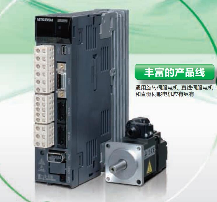
MITSUBISHI HC-UP202 Market price | HC-UP202 Introduction
MITSUBISHI HC-UP202
MITSUBISHI inverter series: FR-A820.
Voltage level: three phase 200V.
Power: 3.7kw.
SLD converter rated current: 25A.
Structure and function: Standard model.
Type: CA.
Substrate coating: have.
Parameters can be selected by 4 different rated current and different overload rating (SLD (ultra light load) rated, LD (light load) rating, ND (general load) rating, HD (weight).
Type load) for selection.
You can choose the most suitable frequency converter for use; and by selecting a transducer with a SLD or LD rated level,
Be able to reduce the size of the device (compared with the FR-A700 series, to reduce the volume of equipment) HC-UP202
For applications that require high torque at low speeds, the HD rating is the most suitable.
The controller is used to control and monitor the frequency converter through the network.
Standard corresponding RS-485 communication (MITSUBISHI converter protocol, Modbus-RTU protocol) data transmission speed up to 115200bps. Output type: transistor source.
Output points: 16 points.
Load voltage: DC12/24.
Load current: 0.8A.
Connection mode: terminal row.
Common public end points: 8.
Switching value, also known as logic, refers to only two values, 0 or 1, ON or OFF.
It is the most common control, it is the advantage of PLC control,
Is also the most basic application of PLC.
Switch volume control is designed to,
According to the current input combination of the switch quantity and the history of the input sequence,
So that PLC generates the corresponding switching output,
In order to make the system work in a certain order.
So, sometimes also known as the order control.
And sequential control is divided into manual, semi-automatic or automatic.
And the control principle is decentralized, centralized and hybrid control three. MITSUBISHI PLC online debugging.
On-line debugging is the process that will through the simulation debugging to further carry on the on-line unification to adjust.
On-line debugging process should be step by step,
From MITSUBISHI PLC only connected to the input device, and then connect the output device, and then connect to the actual load and so on and so on step by step.
If you do not meet the requirements, the hardware and procedures for adjustment.
Usually only need to modify the part of the program can be.
HC-UP202 Operation manual / Instructions / Catalog download link: /searchDownload.html?Search=HC-UP202&select=5
...more relevant model market price >>>>
Related products
MITSUBISHI
Low inertia medium and small capacity motor
HC-UF43
Motor series: low inertia, medium and sm
MITSUBISHI
Flat medium power servo motor
HC-UP202
Servo motor series: flat type, medium po
MITSUBISHI
Low inertia medium and small capacity motor
HC-UF72B
Motor series: low inertia, medium and sm
MITSUBISHI
Low inertia medium and small capacity motor
HC-UF202
Motor series: low inertia, medium and sm
Related download


 next one:
  Last one: