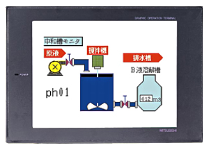
A956GOT-TBD-M3 6 inch man machine interface MITSUBISHI A956GOT-TBD-M3

MELSECNET/10.
Inter-PC fiber loop.
Series Name: A956GOT.
Size: 6 inches.
Resolution: 320 * 240.
Display equipment: high brightness TFT color display.
Display color: 256 color.
Power supply: DC24V.
Memory card: 3M.
The external model design model of creating the system function is mainly to consider the data structure, the overall structure and the process deescription of the software,
The interface design is usually only used as accessories, only on the user''s situation (including age, gender, mental status, education level, personality, ethnic background and etc A956GOT-TBD-M3 A956GOT-TBD-M3.) to understand, to design an effective user interface;
According to the user model of the future system of the end user (for short),
In the end, it is consistent with the system image (external characteristic) of the system after the system is realized,
Users can be satisfied with the system and be able to use it effectively;
When the user model is established, the information given by the system should be considered,
System mapping must accurately reflect the syntax and semantic information of the system A956GOT-TBD-M3 MITSUBISHI A956GOT-TBD-M3.
In short, only to understand the user, to understand the task in order to design a good man-machine interface. RS-232 1 channels.
With DC input 2 points.
Transistor output 2.
Number of stations: 1 stops.
Station type: intelligent equipment station MITSUBISHI A956GOT-TBD-M3.
MITSUBISHI PLC online debugging.
On-line debugging is the process that will through the simulation debugging to further carry on the on-line unification to adjust.
On-line debugging process should be step by step,
From MITSUBISHI PLC only connected to the input device, and then connect the output device, and then connect to the actual load and so on and so on step by step MITSUBISHI A956GOT-TBD-M3.
If you do not meet the requirements, the hardware and procedures for adjustment.
Usually only need to modify the part of the program can be.
MITSUBISHI PLC hardware implementation
Hardware implementation is mainly for the control cabinet and other hardware design and field construction.
Design control cabinet and the operating table and other parts of the electrical wiring diagram and wiring diagram.
Electrical interconnection diagram of each part of the design system.
According to the constructioon drawings of the site wiring, and carry out a detailed inspection A956GOT-TBD-M3.
Because the program design and hardware implementation can be carried out at the same time,
So the design cycle of the MITSUBISHI PLC control system can be greatly reduced.
Related supply information
